The patent we'll look at is US 8,698,473, uninformatively titled "Switching Regulator", from Takeshi Kimura of Yokohama, Japan, assigned to Spansion LLC here in my home town of Sunnyvale, CA. If you like picturesque places, you should visit Yokohama rather than Sunnyvale, preferably the Yokohama that never actually existed, as depicted in Goro Miyazaki's From Up On Poppy Hill. No one appears to have spent their time reading patents up on Poppy Hill.
US 8,698,47 is a pretty typical patent: a modest variation on an existing class of products. The topic is a device that converts one electrical voltage to another. For example, a device like the one described could convert the 3.7 volts it gets from a battery in a cellphone into 1.8 volts needed by the interface that the parts in the phone use to talk to each other.
The normal way to look at this application is to focus on the "inventive concept", whatever the heck that is. Instead, in the proposed claimless patent system, we will focus on what you tell a person of ordinary skill in the relevant art to do in order to make the patented thing, and how that set of instructions differs from any previous set. Kimura provides a particularly convenient example that does exactly that, at least if you happen to know something about electrical block diagrams, which a person of ordinary skill in this art certainly would. (For readers whose expertise is thankfully elsewhere, rest assured: you only need to know that the right person would understand what the funny symbols are, not that you do.)
Figure 1 below shows what's called a block diagram for an electrical part. (The figures shown are simplified and annotated versions of Kimura's Figures 1 and 12.) The various funny symbols represent electrical components that do something useful, like resisting the flow of current, storing charge, or amplifying a signal (making it bigger). Each line with dots on the ends represents a wire that conducts electricity between places in the circuit. "VIN" is the input voltage, to be converted to some other voltage "VOUT" (e.g. from 3.7 to 1.8 volts). This picture is an instruction set, telling our skilled person what components they need and how the components are to be connected together.
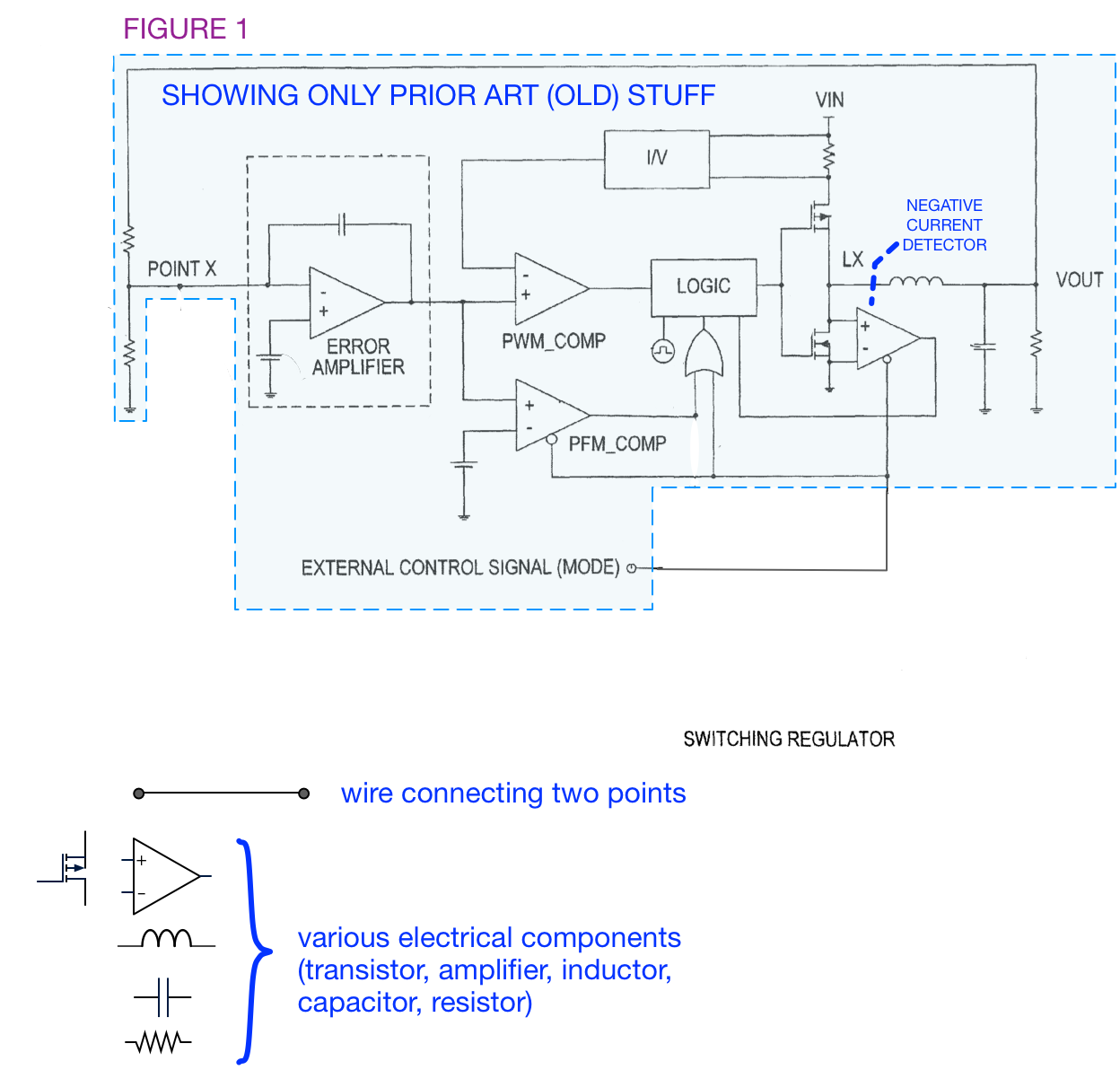
If Kimura's converter were to be built using discrete parts (that is, individual resistors and capacitors with wires, like the ones you can still find at Radio Shack), the instructions would also include a bill of materials. The Bill of Materials, or BOM for short, is a long list that tells someone how to buy the parts you need. For each part, there's typically a vendor, a model or part number, and optionally some specifications and pricing. If Kimura's converter were an integrated circuit, constructed as a chip on a silicon wafer, the bill of materials would be at least partially replaced by a specification for each component: how big a transistor to use, what value of resistance is needed for a resistor, and so on. In modern integrated circuit design, many parts are already available as libraries of designs, so the specification might also include something similar to the BOM, describing which library to use, and which named design to place in the circuit. For simplicity, we'll stick to the discrete-part approach below.
So the instructions provided to our skilled person for the prior art stuff would be, for example, the schematic diagram above, and a bill of materials for the parts, or a set of specifications. The skill of our person of ordinary skill in this art is to turn that set of instructions into a product that works as intended. Note that, even if you the reader don't understand what you are looking at, Kimura's application has defined for us the person of ordinary skill: a person for whom our Figure 1 DOES make sense and DOES suffice to describe what they are to build. If you hand this diagram to someone and they look blankly at you and ask "does COMP stand for Compromise?" then you've got the wrong person. The definition of a person of ordinary skill is thus testable, an important distinction from the existing patent system.
Figure 2 shows a similarly-cleaned up image with the new stuff added.
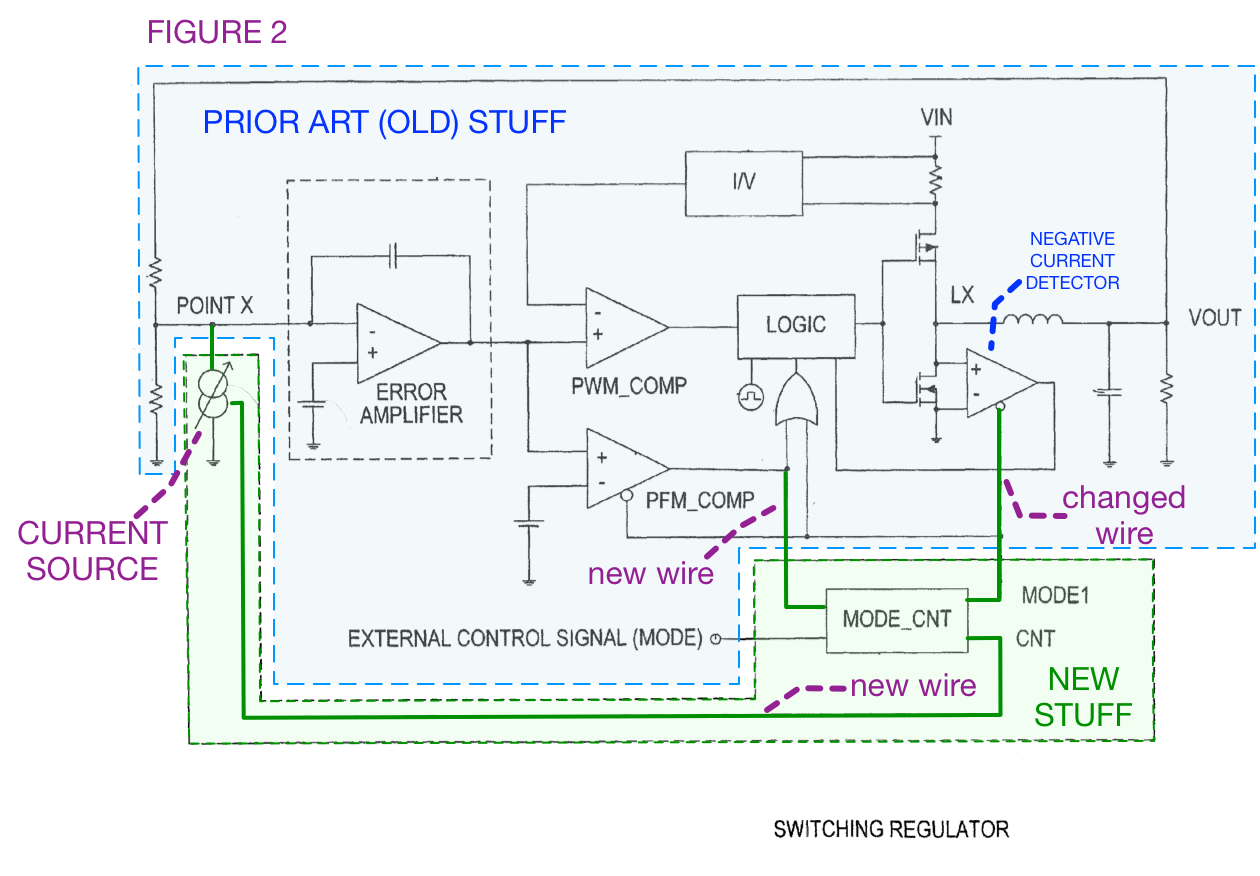
How do these instructions change when we include the new stuff (the stuff in the green-shaded box in Figure 2)? We need to add something like this:
1. Connect a current source [ok, it's actually a current sink in this case, and yes, only EE nerds care] to point X of the schematic. The new wire that connects this source is shown in green in the figure. Current sources have some specifications: the amount of current they conduct, the voltage range over which they work, and so on. This current source can be switched on and off, so we'd provide some other specifications: how much current is carried when the switch is off, how fast the switch turns on and off, and how you control the state of the switch. The other side of the current source is connected to ground, the reference voltage for all other voltages (typically e.g. the case of an instrument).
2. Connect a new wire to switch the current source on and off, also shown in green. Note that in order to implement this switchability, we have to describe how the wire controls the switch in the current source, and when the switch is to be on or off.
3. Connect a new (green) wire to the wire marked "PFM_COMP". Again we need to define what this wire does (in this case, carry a logic signal), and when that signal would be HIGH (a logical YES or 1) and LOW (a logical NO or 0).
4. Change the definition of the wire that used to connect to the little bubble on the Negative Current Detector box (a comparator, and no, COMP doesn't stand for compromise, in case you were wondering): we have a different specification for when this wire is HIGH or LOW than in the prior art diagram.
The need for each of the specifications that define e.g. the current source is part of the prior art. Once I tell you I need a current source, the first thing you ask is "how much current?", and the second thing is "over what voltage range?" Anywhere we need a current source, everyone we will work with knows we need to provide the specs for it. So the part that's different is the fact that we are connecting a current source to point X, where no such current source existing in the prior version. That's one new instruction. The details of the instruction are (in this case) all known prior art; the only new part is the existence of the component at this place. So we count this as one new thing. Like the kid with the block building, our person of ordinary skill needs to know what a current source is and how to get one that works. We just need to tell them where to put it.
Similarly, each new or changed wire needs a specification describing what it is up to. Everyone who can read one of these silly diagrams knows that if I put a wire somewhere I need to tell you what it is doing. That's part of the prior art. So each new wire is one new thing, carrying with it the questions whose answers are needed to make the new part work.
Note that the box marked "MODE_CNT" isn't counted as new, even though it was not present in prior art diagram in Figure 1. The MODE_CNT box is a known method of making sure that the wires do what they are supposed to do. Any other method could be substituted. Implementing it is part of the instructions for the wires.
Thus, when we finish counting, we find that, if we accept Kimura's representation of what the prior art is, then we have added four new instructions to something that existed before. The Hamming distance of this invention is four instructions from the prior art.
Note that we're not making assertions about what is obvious, only what is new. We are assuming a specific set of skills for the people who receive the instructions. This is a verifiable set of assumptions. The description of the prior art defines for us the person we are looking for: a person who can read Figure 1 and turn it into a working voltage converter. This person then needs to be able to implement the new voltage converter when provided with the four additional instructions.
Now, imagine I read Kimura's patent, and happened to have an old converter lying around on my desk (e.g. left over from my failed plot to take over the world using self-assembling robots, abandoned when it turned out the robots ran on 5 V and I only had 9 V power supplies). I could disassemble that converter. Let's imagine that I found that it had all the same parts, or functionally equivalent parts, as those shown in Figure 1. In addition, it had a current source as shown in Figure 2, but not the new wires connected to PFM_COMP and the Negative Current Detector (or their equivalents). Then I would have shown that the correct distance to the prior art was only 2 instructions instead of 4. That narrows the scope of Kimura's claimless patent, and makes it easier for me to improve it enough to no longer infringe. The more new instructions a patent has, the more space it protects for its owner. Claimless patents block copying but not progress.
In the next post (the final one for this series), we'll examine the issues that arise in trying to implement claimless patenting: how to choose the hierarchical level at which an instruction is defined, how to verify the efficacy of the instruction set, and how the choices made may differ from one area of art to another.


